FDTDを試してみます(FDTDによるH面誘電体装荷共振器のSパラメータの計算)
ここ数か月、周期構造導波路のFEMが面白くて色々試してみましたが、関連の文献を当たると圧倒的にFDTDを用いたシミュレーションが多いなあと思いました。
ちょっと試したくなったので、Octaveを使って実装してみました。
FDTDで魅力的だと思ったのはパルス励振で伝送回路の周波数特性を計算できるということです。そこで、2次元FDTDをH面導波管に適用した場合を実装してみました。
H面誘電体装荷共振器
下記のような遮断導波管内に誘電体を装荷したH面導波管回路を解析します。
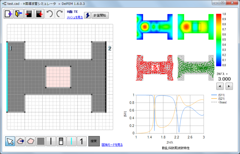
これは、自作の「H面導波管シミュレータ x DelFEM」で計算した結果です。
2次元FDTD
図面(比誘電率の分布)
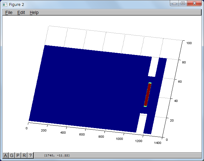
入力導波管をかなり長くとっているのは、入射波と反射波を分離するためです。恐らくもっとまともな方法があると思いますが、今後対応していこうと思います。
素のガウシアンパルスを励振した場合
入力パルスとしては、素のガウシアンパルスを採用してみました。
Ez(t) = E(y) exp( - (t - delay) ^ 2 / (4 * Tp^2))
delay = 120.0 dt
Tp = 30.0 dt / 2
dt = 0.5 /[c0 √{ (1/dx)^2 + (1/dy)^2 } ]
c0:真空中の光速
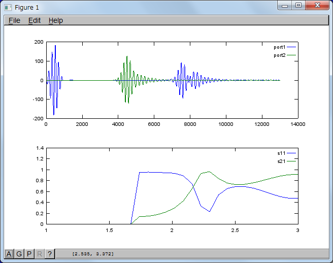
このときのS11、S21の計算結果は以下のようになりました。
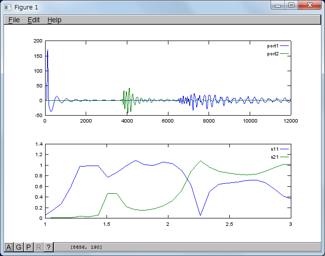
図中、上側はポート1、ポート2の観測点での電界の時間変化Ez(t)|x = xiです。 ここでxi : (i = 1, 2)ポートiの観測点X座標で、横軸の時刻は時間刻み幅dtで規格化しています。さて、反射係数S11、透過係数S21はつぎのように求めました。
S11(f) = Er(f) / Einc(f)
S21(f) = Et(f) / Einc(f)
入射波のスペクトルEinc(f)は、ポート1のEz(t) | x = x1の反射波が到達する前までの期間を取り出してFFTを実行して取得しました。反射波のスペクトルEr(f)は、ポート1のEz(t)|x = x1の反射波が到達する直前以降の期間を取り出してFFTを実行して取得しました。Ez(t)は、ポート2のEz(t) | x = x2の透過波が到達する直前以降の期間を取出しFFTを実行して取得しました。抽出期間は、入射波の抽出期間に合わせています。
このようにして計算した結果が図の下側のグラフになります。
周波数の間隔が粗いですが、FEMで計算した結果と同じく2W/λ = 1.55付近に共振点が現れました。
正弦波変調ガウシアンパルスを励振した場合
E(t) = E(y) exp { - (t - delay)^2 / (2 * Tp) } sin {ωc (t - delay) }
ωc = 2πfc = 2π c0 / λc
Tc = 1 / fc
delay = (5 / 2) * Tc
Tp = Tc / (2 √{ 2 ln(2) }
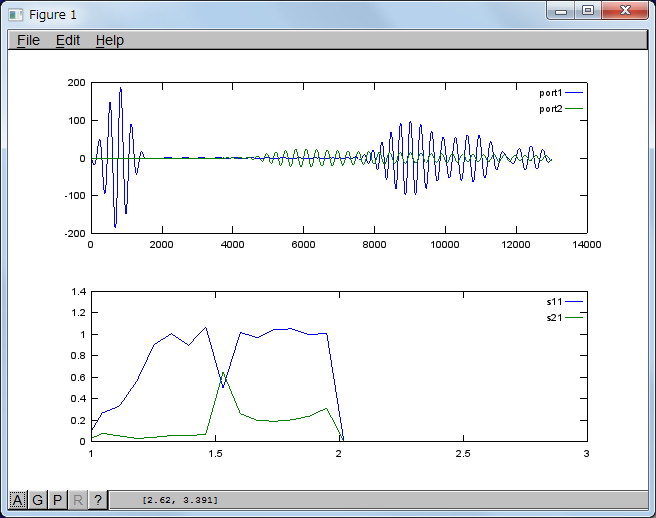
搬送波の規格化周波数fnc (= 2W/λc) を1.5、2.5としたときの計算結果を示します。
fnc = 1.5のとき
fnc = 2.5のとき
2つの計算結果をFEMの結果と見比べると、よく一致していることが確認できます。
wg2d_dielectric_filer.m
###########################################################
#  TE波(TMz) 導波管誘電体共振器
#
#  coded by ryujimiya April 2013
###########################################################
function [ndivX, ndivY, distanceX, distanceY, ...
          qzz, pxx, pyy, ...
          Ez, Hx, Hy, timeAry, ...
          EzTimePort1, EzTimePort2] = fdtd_2d_TMz(loopCnt)
    #---------------------------------------------
    # 定数
    #---------------------------------------------
    eps0 = 8.8541878e-12;
    c0 = 2.99792458e8;
    mu0 = 4.0e-7 * pi;

    #---------------------------------------------
    # 領域
    #---------------------------------------------
    ndivPerUnit = 4;
    ndivX1 = 280 * ndivPerUnit;
    ndivX2 = 19 * ndivPerUnit;
    ndivX3 = 20 * ndivPerUnit;
    ndivX = ndivX1 + ndivX2 + ndivX3;
    ndivY1 = 20 * ndivPerUnit;
    ndivY2 = 10 * ndivPerUnit;
    ndivY = ndivY1;
    ndivYOfs = (ndivY1 - ndivY2) / 2;
    distanceX = 3.0e-3 * ndivX;
    distanceY = 3.0e-3 * ndivY;

    #---------------------------------------------
    # 分割幅の逆数
    #---------------------------------------------
    dx = distanceX / ndivX;
    dy = distanceY / ndivY;
    cx = 1.0 / dx;
    cy = 1.0 / dy;
    dt = 0.5 * 1.0 / (c0 * sqrt(cx * cx + cy * cy));

    #---------------------------------------------
    # 初期化
    #---------------------------------------------
    Ez = zeros(ndivX + 1, ndivY + 1);
    Hx = zeros(ndivX + 1, ndivY);
    Hy = zeros(ndivX, ndivY + 1);
    # 比透磁率の逆数
    pxx = ones(ndivX + 1, ndivY);
    pyy = ones(ndivX, ndivY + 1);
    # 比誘電率の逆数
    qzz = ones(ndivX + 1, ndivY + 1);

    # 吸収境界条件で使用する界
    prevHx1 = zeros(ndivY, 1);  # 境界1 + dx
    prevHx2 = zeros(ndivY, 1);  # 境界2 - dx
    prevEz1 = zeros( (ndivY + 1), 1);  # 境界1 + dx
    prevEz2 = zeros( (ndivY + 1), 1);  # 境界2 - dx

    # ポート上の1節点の界の時間変化
    timeAry = zeros(loopCnt, 1);
    EzTimePort1 = zeros(loopCnt, 1);
    EzTimePort2 = zeros(loopCnt, 1);

    #---------------------------------------------
    # 励振源
    #---------------------------------------------
    # 周波数
    #freq = 5.0e+9;
    freq = 1.5 * c0 / (2.0 * distanceY);
    #freq = 2.5 * c0 / (2.0 * distanceY);
    # 角周波数
    omega = 2.0 * pi * freq;
    # 波長
    waveLength = c0 / freq;
    # 波数
    k0 = 2.0 * pi / waveLength;
    # 平面波インピーダンス
    z0 = sqrt(mu0 / eps0);

    # 励振源の位置
    srcPosX = 5;

    # 付加励振源のY方向界分布
    srcProfileY = [];
    # 付加励振源のY方向界分布
    srcProfileY = zeros( (ndivY + 1), 1);
    for i = 1: (ndivY + 1)
        srcProfileY(i) = sin( (pi/ndivY) * (i - 1));  # TE波(導波管TE10モード)
    endfor

    # 伝搬定数(X方向)
    betaX = sqrt(k0 * k0 - (pi / distanceY) * (pi / distanceY));  # TE波(導波管TE10モード)
    # 伝搬定数(Y方向) 自由空間の場合に使用
    betaY = k0; # 平面波
    # 界インピーダンス
    zf = (omega * mu0) / betaX;  # TE波

    # ガウシアンパルス
    #isGaussianPulse = false;
    isGaussianPulse = true;
    typeGaussian = 0;  # 素のガウシアンパルス
    #typeGaussian = 2; # 正弦波変調
    if (typeGaussian == 0)
        # 素のガウシアンパルス
        # 遅延
        delay = 120.0 * dt;
        # バルス幅(半分)
        Tp = 30.0 * dt / 2.0;
    elseif (typeGaussian == 1)
        # 微分ガウシアンパルス
        assert(false);
    elseif (typeGaussian == 2)
        # 正弦波変調
        nCycle = 5;
        delay = (1.0 / freq) * nCycle / 2;
        Tp = delay / (2.0 * sqrt(2.0 * log(2.0)));
    else
        assert(false);
    endif

    nTp = Tp / dt;
    ndelay = delay / dt;

    # ポート観測位置
    port1PosX = srcPosX + 2;
    port1PosY = floor(ndivY / 2);
    port2PosX = ndivX - 2;
    port2PosY = floor(ndivY / 2);

    printf("waveguide TMz(TE) : isGaussianPulse %d typeGaussian %d\n", isGaussianPulse, typeGaussian);
    printf("nTp: %d  ndelay: %d\n", nTp, ndelay);
    #assert(false);

    #---------------------------------------------
    # 媒質設定
    #---------------------------------------------
    # 境界条件  Ez = qzz Dz
    # ポート1導波路
    # 上下の導体
    qzz(1:(ndivX1 + 1), 1) = 0.0;
    qzz(1:(ndivX1 + 1), (ndivY + 1)) = 0.0;
    # 不連続部
    # 上下の導体
    qzz( (ndivX1 + 1):(ndivX - ndivX3 + 1), 1:(ndivYOfs + 1)) = 0.0;
    qzz( (ndivX1 + 1):(ndivX - ndivX3 + 1), (ndivY - ndivYOfs + 1):(ndivY + 1)) = 0.0;
    # ポート2導波路
    # 上下の導体
    qzz( (ndivX - ndivX3 + 1):(ndivX + 1), 1) = 0.0;
    qzz( (ndivX - ndivX3 + 1):(ndivX + 1), (ndivY + 1)) = 0.0;
#qzz(:, 1) = 0.0;
#qzz(:, (ndivY + 1)) = 0.0;

    # 散乱オブジェクト
    scatterEr = 2.62;
    #scatterEr = 1.00;
    scatterPosX = ndivX1 + 6 * ndivPerUnit + 1;
    scatterPosY = ndivYOfs + 2 * ndivPerUnit + 1;
    scatterLenX = 7 * ndivPerUnit;
    scatterLenY = 6 * ndivPerUnit;

    # 左下
    qzz(scatterPosX, scatterPosY) = 1.0 / ( (1.0 + 1.0 + 1.0 + scatterEr) / 4.0);
    # 左上
    qzz(scatterPosX, (scatterPosY + scatterLenY)) = 1.0 / ( (1.0 + 1.0 + 1.0 + scatterEr) / 4.0);
    # 右下
    qzz( (scatterPosX + scatterLenX), scatterPosY) = 1.0 / ( (1.0 + 1.0 + 1.0 + scatterEr) / 4.0);
    # 右上
    qzz( (scatterPosX + scatterLenX), (scatterPosY + scatterLenY)) = 1.0 / ( (1.0 + 1.0 + 1.0 + scatterEr) / 4.0);
    # 左境界
    qzz(scatterPosX, (scatterPosY + 1):(scatterPosY + scatterLenY - 1)) = 1.0 / ( (1.0 + scatterEr) / 2.0);
    # 右境界
    qzz( (scatterPosX + scatterLenX), (scatterPosY + 1):(scatterPosY + scatterLenY - 1)) = 1.0 / ( (1.0 + scatterEr) / 2.0);
    # 下境界
    qzz( (scatterPosX + 1):(scatterPosX + scatterLenX - 1), scatterPosY) = 1.0 / ( (1.0 + scatterEr) / 2.0);
    # 上境界
    qzz( (scatterPosX + 1):(scatterPosX + scatterLenX - 1), (scatterPosY + scatterLenY)) = 1.0 / ( (1.0 + scatterEr) / 2.0);
    # 内部
    qzz( (scatterPosX + 1):(scatterPosX + scatterLenX - 1), (scatterPosY + 1):(scatterPosY + scatterLenY - 1)) = 1.0 / scatterEr;
#disp(qzz( (scatterPosX):(scatterPosX + scatterLenX), (scatterPosY):(scatterPosY + scatterLenY)));
#assert(false);

    # 境界条件
    #  Hy = pyy By
    # ポート1導波路
    # 上下の導体
    pyy(1:(ndivX1), 1) = 0.0;
    pyy(1:(ndivX1), (ndivY + 1)) = 0.0;
    # 不連続部
    # 上下の導体
    pyy( (ndivX1 + 1):(ndivX - ndivX3), 1:(ndivYOfs + 1)) = 0.0;
    pyy( (ndivX1 + 1):(ndivX - ndivX3), (ndivY - ndivYOfs + 1):(ndivY + 1)) = 0.0;
    # ポート2導波路
    # 上下の導体
    pyy( (ndivX - ndivX3 + 1):(ndivX), 1) = 0.0;
    pyy( (ndivX - ndivX3 + 1):(ndivX), (ndivY + 1)) = 0.0;
#pyy(:, 1) = 0.0;
#pyy(:, (ndivY + 1)) = 0.0;
#assert(false);

    #---------------------------------------------
    # Yeeアルゴリズム
    #---------------------------------------------
    for n = 1:loopCnt
        # 電界
        Ez(2:ndivX, 2:ndivY) = Ez(2:ndivX, 2:ndivY) + (dt / eps0) * qzz(2:ndivX, 2:ndivY) .* ( ...
            (Hy(2:ndivX, 2:ndivY) - Hy(1:(ndivX - 1), 2:ndivY)) * cx - (Hx(2:ndivX, 2:ndivY) - Hx(2:ndivX, 1:(ndivY - 1))) * cy ...
            );

        # 励振
        # 付加励振源:モード励振
        if (isGaussianPulse)
          # なし
        else
            #for i = 2 : ndivY
            for i = 1 : (ndivY + 1)
                srcHy = - 1.0 * srcProfileY(i) * sin(omega * (n) * dt - betaX * dx * 0.5); # 進行波
                #srcHy = srcProfileY(i) * sin(omega * (n) * dt + betaX * dx * 0.5); # 後進波
                Ez(srcPosX, i) = Ez(srcPosX, i) - (dt / eps0) * (srcHy * cx);
            endfor
        endif

        # Murの吸収境界条件
        vpx = (omega / betaX);
        # 左の境界
        workEzb1 = getRowVec(Ez, 1); # 境界1
        workEz1 = getRowVec(Ez, 2); # 境界1 + dx
        workEzb1(:) = prevEz1(:) + (vpx * dt - dx) / (vpx * dt + dx) * (workEz1(:) - workEzb1(:));
        # 上下の導体
        workEzb1(1) = 0;
        workEzb1(ndivY + 1) = 0;
        prevEz1(:) = workEz1(:);
        Ez = setRowVec(Ez, 1, workEzb1); # 境界1
        # 右の境界
        workEzb2 = getRowVec(Ez, ndivX + 1); # 境界2
        workEz2 = getRowVec(Ez, ndivX); # 境界2 - dx
        workEzb2(:) = prevEz2(:) + (vpx * dt - dx) / (vpx * dt + dx) * (workEz2(:) - workEzb2(:));
        # 上下の導体
        workEzb2(1) = 0;
        workEzb2(ndivY + 1) = 0;
        prevEz2(:) = workEz2(:);
        Ez = setRowVec(Ez, ndivX + 1, workEzb2); # 境界2

        # 磁界
        Hx(2:ndivX, :) = Hx(2:ndivX, :) - (dt / mu0) * pxx(2:ndivX, :) .* ( ...
            (Ez(2:ndivX, 2:(ndivY + 1)) - Ez(2:ndivX, 1:ndivY)) * cy ...
            );
        Hy(:, 2:ndivY) = Hy(:, 2:ndivY) - (dt / mu0) * pyy(:, 2:ndivY) .* ( ...
            -(Ez(2:(ndivX + 1), 2:ndivY) - Ez(1:ndivX, 2:ndivY)) * cx ...
            );

        # 励振
        # 付加励振源:モード励振
        if (isGaussianPulse)
            #for i = 2: ndivY
            for i = 1: (ndivY + 1)
                srcEz = 0.0;
                if ( (n + 0.5) <= floor(2.0 * ndelay + 1.0))
                    if (typeGaussian == 0)
                        srcEz =  srcProfileY(i)  ...
                                    * exp(-1.0 * (n + 0.5 - ndelay) * (n + 0.5 - ndelay)/(4.0 * nTp * nTp));
                    elseif (typeGaussian == 1)
                        assert(false);
                    elseif (typeGaussian == 2)
                        srcEz =  srcProfileY(i) * sin(omega * (n + 0.5 - ndelay) * dt) ...
                                    * exp(-1.0 * (n + 0.5 - ndelay) * (n + 0.5 - ndelay)/(2.0 * nTp * nTp));
                    else
                        assert(false);
                    endif
                else
                    srcEz = 0.0;
                endif
                srcEz = srcEz * z0;  # 特性インピーダンスを掛けておく(磁界の振幅を1にする)
                Hy(srcPosX, i) = Hy(srcPosX, i) - (dt / mu0) * (srcEz * cy);
            endfor
        else
            #for i = 2: ndivY
            for i = 1: (ndivY + 1)
                srcEz = zf * srcProfileY(i) * sin(omega * (n + 0.5) * dt);
                Hy(srcPosX, i) = Hy(srcPosX, i) - (dt / mu0) * (srcEz * cy);
            endfor
        endif

        # Murの吸収境界条件
        vpx = (omega / betaX);
        # 左の境界
        workHxb1 = getRowVec(Hx, 1); # 境界1
        workHx1 = getRowVec(Hx, 2); # 境界1 + dx
        workHxb1(:) = prevHx1(:) + (vpx * dt - dx) / (vpx * dt + dx) * (workHx1(:) - workHxb1(:));
        prevHx1(:) = workHx1(:);
        Hx = setRowVec(Hx, 1, workHxb1); # 境界1
        # 右の境界
        workHxb2 = getRowVec(Hx, ndivX + 1); # 境界2
        workHx2 = getRowVec(Hx, ndivX); # 境界2 - dx
        workHxb2(:) = prevHx2(:) + (vpx * dt - dx) / (vpx * dt + dx) * (workHx2(:) - workHxb2(:));
        prevHx2(:) = workHx2(:);
        Hx = setRowVec(Hx, ndivX + 1, workHxb2); # 境界2

        # ポート観測点の界を格納
        timeAry(n) = n * dt;
        EzTimePort1(n) = Ez(port1PosX, port1PosY);
        EzTimePort2(n) = Ez(port2PosX, port2PosY);
    endfor;

endfunction


#-------------------------------------------------------
# rowベクトルを取得する
#-------------------------------------------------------
function vec = getRowVec(ary, rowIndex)
    arySize = size(ary);
    rowSize = arySize(1);
    colSize = arySize(2);
    vec = zeros(colSize, 1);
    for i = 1 : colSize
        vec(i) = ary(rowIndex, i);
    endfor
endfunction

#-------------------------------------------------------
# rowベクトルを配列に格納する
#-------------------------------------------------------
function retAry = setRowVec(ary, rowIndex, vec)
    arySize = size(ary);
    rowSize = arySize(1);
    colSize = arySize(2);
    retAry = ary;
    for i = 1 : colSize
        retAry(rowIndex, i) = vec(i);
    endfor
endfunction

#-------------------------------------------------------
# colベクトルを取得する
#-------------------------------------------------------
function vec = getColVec(ary, colIndex)
    arySize = size(ary);
    rowSize = arySize(1);
    colSize = arySize(2);
    vec = zeros(rowSize, 1);
    for i = 1 : rowSize
        vec(i) = ary(i, colIndex);
    endfor
endfunction

#-------------------------------------------------------
# colベクトルを配列に格納する
#-------------------------------------------------------
function retAry = setColVec(ary, colIndex, vec)
    arySize = size(ary);
    rowSize = arySize(1);
    colSize = arySize(2);
    retAry = ary;
    for i = 1 : rowSize
        retAry(i, colIndex) = vec(i);
    endfor
endfunction
呼び出し側
###########################################################
#  TE波(TMz) 導波管誘電体共振器
#
#  coded by ryujimiya April 2013
###########################################################
# ウィンドウをすべて閉じる
close all;
# メモリを解放する
clear all;

#------------------------------------------------------------------
# settings
#------------------------------------------------------------------
#素のガウシアンパルス
loopCnt = 12000;
samplingCnt = 6000;
inputStartCnt = 1;
reflectStartCnt = 6000;
transStartCnt = 3500;
#正弦波変調
#  normalizedfreq : 1.5
#loopCnt = 13000;
#samplingCnt = 6500;
#inputStartCnt = 1;
#reflectStartCnt = 6500;
#transStartCnt = 4500;
#  normalizedFreq : 2.5
#loopCnt = 13000;
#samplingCnt = 6500;
#inputStartCnt = 1;
#reflectStartCnt = 6500;
#transStartCnt = 3500;

assert(reflectStartCnt >= samplingCnt);
assert(reflectStartCnt + (samplingCnt - 1) < loopCnt);
assert(transStartCnt + (samplingCnt - 1) < loopCnt);

#------------------------------------------------------------------
# FDTD calculation
#------------------------------------------------------------------
# TMz
source "wg2d_dielectric_filter.m";
[ndivX, ndivY, distanceX, distanceY, ...
    qzz, pxx, pyy, ...
    Ez, Hx, Hy, timeAry, ...
    EzTimePort1, EzTimePort2] = fdtd_2d_TMz(loopCnt);

#------------------------------------------------------------------
# FFT function
#------------------------------------------------------------------
function [f, fd, pd] = fft_field(tAryAll, waveAryAll, n1, n2, showFlg)
    tAry = tAryAll(n1:n2);
    waveAry = waveAryAll(n1:n2);
    dt = tAry(2) - tAry(1);

    # フーリエ変換
    dataCnt = length(waveAry);
    fd = fft(waveAry) / dataCnt;
    # フーリエ振幅
    spec = abs(fd);
    # パワースペクトルの計算
    #  .*(要素同士のかけ算)とconj(共役複素数)
    pd = fd .* conj(fd);

    # 時間長さ
    tl = dt * dataCnt;
    # 周波数刻み
    df = 1.0 / tl;
    # 周波数刻みの値をを行列で作成
    f = (0:(dataCnt - 1)) * df;

    if (showFlg)
        # 波形表示
        subplot(2, 1, 1); # 上側
        plot(tAry, waveAry);
        # スペクトルを表示
        subplot(2, 1, 2); # 下側
        # パワースペクトルとフーリエ振幅)の表示
        plot(f, spec, "-;fd;", f, pd, "-;pd;");
    endif
endfunction

#------------------------------------------------------------------
# plpt s11 & s21 function
#------------------------------------------------------------------
function plot_s_parameters( ...
    waveguideWidth, samplingCnt, inputStartCnt, reflectStartCnt, transStartCnt, ...
    tAry, waveAryPort1, waveAryPort2)
    # 定数
    c0 = 2.99792458e8;

    # check
    #plot(tAry / (tAry(2)- tAry(1)), waveAryPort1, "-;port1;", ...
    #    tAry / (tAry(2)- tAry(1)), waveAryPort2, "-;port2;");

    # 離散フーリエ変換を実行する
    n1_1 = inputStartCnt;
    n1_2 = n1_1 + (samplingCnt - 1);
    n1r_1 = reflectStartCnt;
    n1r_2 = n1r_1 + (samplingCnt - 1);
    n2_1 = transStartCnt;
    n2_2 = n2_1 + (samplingCnt - 1);
    assert(n1_2 <= length(tAry));
    assert(n1r_2 <= length(tAry));
    assert(n2_2 <= length(tAry));
    [freq1, fd1, pd1] = fft_field(tAry, waveAryPort1, n1_1, n1_2, false);
    [freq1r, fd1r, pd1r] = fft_field(tAry, waveAryPort1, n1r_1, n1r_2, false);
    [freq2, fd2, pd2] = fft_field(tAry, waveAryPort2, n2_1, n2_2, false);
    assert(length(freq1) == length(freq1r));
    assert(length(freq1) == length(freq2));
    assert(length(freq1) == length(fd1));
    assert(length(freq1) == length(fd1r));
    assert(length(freq1) == length(fd2));
    assert(length(freq1) == length(pd1));
    assert(length(freq1) == length(pd1r));
    assert(length(freq1) == length(pd2));
    #plot(freq1, pd1);
    #plot(freq1, pd1r);
    #plot(freq2, pd2);

    # 切り捨てる値を決める
    thVal = 0.0;
    maxPd = 0.0;
    for i = 1:length(pd1)
        if (maxPd < pd1(i))
            maxPd = pd1(i);
        endif
    endfor
    thVal = 0.01 * maxPd;
    assert(abs(maxPd) >= 1.0e-12);
    # 反射係数
    s11Freq = zeros(length(pd1r), 1);
    # 透過係数
    #s21Freq = abs(fd2) ./ abs(fd1);
    #s21Freq = sqrt(pd2) ./ sqrt(pd1);
    s21Freq = zeros(length(pd2), 1);
    for i = 1:length(pd1)
        if (pd1(i) >= thVal)
            s11Freq(i) = sqrt(pd1r(i) / pd1(i));
            s21Freq(i) = sqrt(pd2(i) / pd1(i));
        endif
    endfor
    # 周波数特性の表示
    #freqMax = freq1(length(freq1));
    #plot(freq1, s21Freq);
    #axis([0, freqMax / 2]); # 周波数領域は半分だけ表示
    nFreq = length(freq1) / 2;
    normalizedFreq = zeros(nFreq, 1);
    normalizedFreq(1:nFreq) = freq1(1:nFreq) * 2.0 * waveguideWidth / c0;
    s11FreqHalf(1:nFreq) = s11Freq(1:nFreq);
    s21FreqHalf(1:nFreq) = s21Freq(1:nFreq);
    #plot(normalizedFreq, s11FreqHalf, "-;s11;", normalizedFreq, s21FreqHalf, "-;s21;");
    #axis([1.0, 3.0]);

    subplot(2, 1, 1); # 上側
    plot(tAry / (tAry(2)- tAry(1)), waveAryPort1, "-;port1;", ...
        tAry / (tAry(2)- tAry(1)), waveAryPort2, "-;port2;");
    subplot(2, 1, 2); # 下側
    plot(normalizedFreq, s11FreqHalf, "-;s11;", normalizedFreq, s21FreqHalf, "-;s21;");
    #plot(normalizedFreq, s11FreqHalf, "+;s11;", normalizedFreq, s21FreqHalf, "+;s21;");
    axis([1.0, 3.0]);
endfunction

#------------------------------------------------------------------
# plot s11 & s21
#------------------------------------------------------------------

workWaveAryPort1 = EzTimePort1;
workWaveAryPort2 = EzTimePort2;
# 反射係数,透過係数の計算
plot_s_parameters(distanceY, samplingCnt, inputStartCnt, reflectStartCnt, transStartCnt, timeAry, workWaveAryPort1, workWaveAryPort2);

#------------------------------------------------------------------
# plot function
#------------------------------------------------------------------
function plot_field(fVals, ndiv1, ndiv2)
    x = [ ];
    y = [ ];
    z = [ ];
    for i = 1 : ndiv1
        x(i) = i;
    endfor
    for i = 1 : ndiv2
        y(i) = i;
    endfor

    for i = 1 : ndiv1
        for j = 1 : ndiv2
           z(j, i) = fVals(i, j);
        endfor
    endfor

    figure;
    mesh(x, y, z);
endfunction

#------------------------------------------------------------------
# plot
#------------------------------------------------------------------
# qzz
plot_field((1.0 ./ qzz), ndivX + 1, ndivY + 1);
#TMz
plot_field(Ez, ndivX + 1, ndivY + 1);
plot_field(Hx, ndivX + 1, ndivY);
plot_field(Hy, ndivX, ndivY + 1);
参考にしたページ
(1) 1分で試すフーリエ変換(FFT) Diaspar Journal
http://diaspar-journal.blogspot.jp/2008/11/1fft.html
(2) Octaveによるフーリエ解析 信州大学 田守伸一郎 振動学特論
http://sake03.shinshu-u.ac.jp/tokuron/octave_fft.html
(3) FDTD による電磁波の回折のアニメーション 平野拓一
http://www-antenna.ee.titech.ac.jp/~hira/study/fdtd/diffraction/index-j.html
(4) FDTD Open Source Demo Programs
<文献>
(5) Srikumar Sandeep
"Broadband analysis of microstrip patch antenna using 3D FDTD - UPML"
http://sandeepkumar2006.tripod.com/FDTD3DPatchAntenna.pdf
Term paper ECEN 5134, Fall 2008, University of Colorado at Boulder
素のガウシアンパルスのパラメータを参照しました。
(6) Hung Loui
"1D-FDTD using MATLAB"
http://ecee.colorado.edu/~mcleod/pdfs/NMIP/HW/HW%201%20solution/project1.pdf
ECEN-6006 Numerical Methods In Photonics Project-1, September 2004
変調ガウシアンパルスのパラメータを参照しました。